# Interfaces
This chapter describes the hardware interfaces, and some hardware modules, including Pinout and some guides.
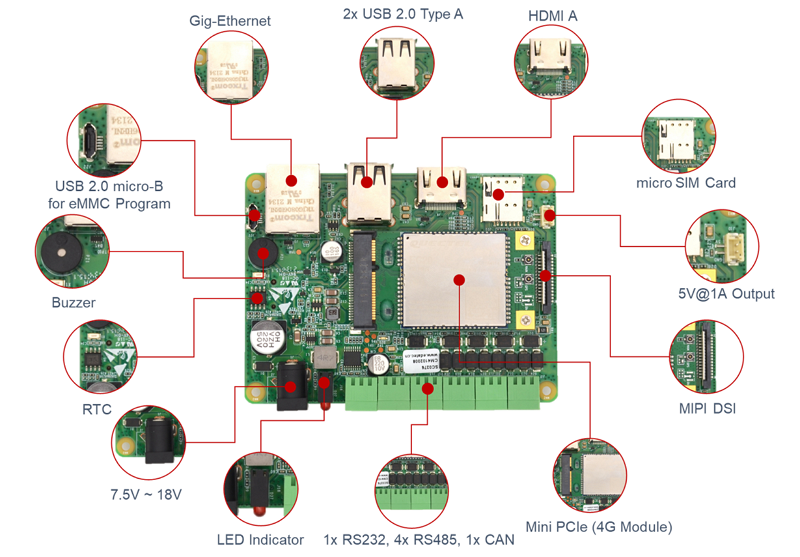
# Interface Diagram
# Top
# Bottom

# System Functions
# micro SDCard
CM4 Sensing support dual-storage solution, eMMC + micro SDCard. eMMC is used for rootfs and micro SDCard can be used for extended data storage.
WARNING
The system can only boot from eMMC and the micor SDCard can be used for data storage only.
If you use the Desktop version of Raspberry Pi OS, the micro SDCard will be automatically mounted and a 'Disk' icon will be added to the Desktop. If you use the Lite version of Raspberry Pi OS, You can use lsblk to detect the block devices and mount to mount the device to a directory.
Detect the Block Device
lsblk

NAME         MAJ:MIN RM  SIZE RO TYPE MOUNTPOINT
mmcblk0      179:0    0 14.6G  0 disk
├─mmcblk0p1  179:1    0  256M  0 part /boot
└─mmcblk0p2  179:2    0 14.3G  0 part /
mmcblk0boot0 179:32   0    4M  1 disk
mmcblk0boot1 179:64   0    4M  1 disk
mmcblk2      179:96   0 14.9G  0 disk
└─mmcblk2p1  179:97   0 14.9G  0 part
lsblk will list all the block devices, including eMMC, micro SDCard, U-Disks. in the above command:
mmcblk0is the eMMC device, and it has 2 partitions. mmcblk0p1 is the boot partition and mmcblk0p2 is the rootfsmmcblk2is the micro SDCard device. It has 1 partition and haven't been mounted.
Mount SDCard partition
Before we read / write the micro SDCard, we should mount its parttions to a directory. Let's take /mnt for example:
sudo mount /dev/mmcblk2p1 /mnt
Then we can read from /mnt or write to /mnt to read write the SD card.
Unmount SDCard partition
sync
sudo umount /mnt
Automatically Mount when System Boot
We can modify fstab to automatically mount the block device when reboot. More details please refer to the manual of fstab.
Reference
# RTC (Real Time Clock)
There is a RTC on CM4 Sensing. To use it, please make sure a CR1220 RTC battery is installed.
In the pre-installed Raspberry Pi OS, the RTC sync service is enabled default. The service can automaticlly sync clock betweeen RTC and system clock:
- When boot up, the service will get the clock from RTC and update the system clock with it
- If CM4 Sensing has Internet accessing, the system clock will sync with the NTP server.
- When system poweroff, the service write the system clock to RTC
- Thanks to the CR1220 battery, the clock is continually running when the CM4 Sensing is turned on or off
In this way, we can get a reliable clock.
TIP
Note: If it is the first time boot up, there is no valid date in RTC, and this will result sync to system clock failed. Don't worry, Just reboot and it will be Okay.
If you don't want this service, you clould disable it manually:
sudo systemctl disable rtc
sudo reboot
Re-enable the service
sudo systemctl enable rtc
sudo reboot
# RTC Manually Operation
Read clock from RTC
sudo hwclock -r
Sync RTC clock to system clock
sudo hwclock -s
Write system clock to RTC
sudo hwclock -w
# Trouble Shooting
First, please check if the RTC device(/dev/rtc0) is loaded:
ls /dev/rtc0
If no, you may use the original Raspberry Pi OS without our BSP installed, Please refer to section: Intall BSP by apt-get to install the BSP package. You may also want to install ed-rtc package to enable RTC automatically sync service.
Some other possible doubts:
- No CR1220 battery installed
- Internet is necessary to sync time from Internet. Besides, you should enable
UDP 123port.
# Display
CM4 Sensing has Triple Display channels and could could feed 2 devices simultaneously.
- If you use the Desktop version of Raspberry Pi OS, you can set it by
Menu -> Preferences -> Screen Configuration - If you use Lite version of Raspberry Pi OS, please refer to xrandr (opens new window)
# Standard HDMI A
CM4 Sensing has a standard HDMI Type A port. Just plug to a HDMI monitor and it will work.
# HDMI FPC Connector
J12 is another HDMI port but in FPC connctor form-factor. It has USB 2.0 signals for touch, PWM for brightness. We are developing a new HDMI Touch Display, you could get in touch with the Sales for the latest status.
# MIPI DSI Connector
J8 is the MIPI DSI connector in FPC form-factor. It supports the official Raspberry Pi 7" Touch Display. We also sale this product, refer to: 7” Touch Display (opens new window)
J10 is a 5V@1A DC power output, it can provide power for the Raspberry Pi 7" Touch Display.
MIPI DSI is enabled default in the pre-installed OS. If you use the origin Raspberry Pi OS, you should intall the BSP package first to use the MIPI DSI. Please refer to section: Intall BSP by apt-get to install the BSP package.
# Wired Interfaces
# Gigabit Ethernet
CM4 Sensing has a 10 / 100 / 1000Mbsp Ethernet. We suggest to use Cat6 Ethernet cable. In Raspberry Pi OS, it uses DHCP to get IP address default. If you want to set a static IP address, please refer to the usage of dhcpcd: manual of dhcpcd (opens new window)
# USB 2.0 Host
CM4 Sensing has 2 USB 2.0 Type A ports. The USB 2.0 Host is default enabled in the pre-installed OS. If you use the origin Raspberry Pi OS, you should intall the BSP package first. Please refer to section: Intall BSP by apt-get to install the BSP package.
# USB micro-B
J22 is the USB micro-B port, it's mainly used for eMMC Flashing. You could also use it to make the CM4 Sensing as a USB peripheral device such as a mass-storage device. For eMMC Flashing, please refer to eMMC Flashing
# Wireless
CM4 Sensing provide rich wireless network support, including Dual-band WiFi, Bluetooth 5.0 and optional 4G LTE.
# Dual-band WiFi
The CM4 Sensing can be supplied with an onboard wireless module supporting both:
- 2.4 GHz, 5.0 GHz IEEE 802.11 b/g/n/ac wireless
- Bluetooth 5.0, BLE
The CM4 Sensing has an onboard antenna. If used it should be positioned in the product such that it is not surrounded by metal, including any ground plane. Alternatively, the CM4 Sensing has an external antenna which is certified when you purchase CM4 Sensing with WiFi and metal case.
# Enable WiFi
You should set the country code for your wireless network before you use. If you use a Desktop OS, please refer to: Raspberry pi Documentation - Configuring Networking - Using the Desktop (opens new window), If you use a Lite version OS, please refer to: Raspberry pi Documentation - Configuring Networking - Using the Command Line (opens new window).
# Internal or External Antenna
WARNING
the default WiFi antenna setting of pre-intalled OS is internal antenna. If you purchase CM4 Sensing WiFi metal case and external antenna, you should update the settings.
Edit /boot/config.txt
sudo nano /boot/config.txt
For external antenna, add:
dtparam=ant2
For internal antenna, add:
dtparam=ant1
# AP
WiFi can also be configured to AP mode.
a Routed Wireless Access Point
                                        +- RPi -------+
                                     +---+ 10.10.0.2   |          +- Laptop ----+
                                     |   |     WLAN AP +-)))  (((-+ WLAN Client |
                                     |   | 192.168.4.1 |          | 192.168.4.2 |
                                     |   +-------------+          +-------------+
                 +- Router ----+     |
                 | Firewall    |     |   +- PC#2 ------+
(Internet)---WAN-+ DHCP server +-LAN-+---+ 10.10.0.3   |
                 |   10.10.0.1 |     |   +-------------+
                 +-------------+     |
                                     |   +- PC#1 ------+
                                     +---+ 10.10.0.4   |
                                         +-------------+
a Bridged Wireless Access Point
                                         +- RPi -------+
                                     +---+ 10.10.0.2   |          +- Laptop ----+
                                     |   |     WLAN AP +-)))  (((-+ WLAN Client |
                                     |   |  Bridge     |          | 10.10.0.5   |
                                     |   +-------------+          +-------------+
                 +- Router ----+     |
                 | Firewall    |     |   +- PC#2 ------+
(Internet)---WAN-+ DHCP server +-LAN-+---+ 10.10.0.3   |
                 |   10.10.0.1 |     |   +-------------+
                 +-------------+     |
                                     |   +- PC#1 ------+
                                     +---+ 10.10.0.4   |
                                         +-------------+
More details please refer to open source project: github: garywill/linux-router (opens new window)
# Bluetooth 5.0
Customers can use bluetoothctl to discover, pair and connect a bluetooth device. Please refer to: ArchLinux - Wiki - Bluetooth (opens new window)
# 4G LTE
The 4G LTE is optional. Customers should use the pre-installed OS. If it's the origin Raspberry Pi OS, Customers should install our BSP package to enable the hardware feature. Please refer to section: Intall BSP by apt-get to install the BSP package, then you should also install ed-networkmanager package.
sudo apt install ed-networkmanager
sudo reboot
# Set the 4G connection
Use this command to set a gsm connection
# sudo nmcli connection add type gsm con-name <connection_name>
# set a gsm connection named mobilegsm
sudo nmcli connection add type gsm con-name mobilegsm
TIP
If the above command does not work, here is some examples, you can follow examples to create a connection
# sudo nmcli connection add type gsm con-name <mobile> ifname cdc-wdm0 gsm.number <number> gsm.apn <apn> gsm.username <username> gsm.password <password>
# China Mobile
sudo nmcli connection add type gsm con-name "mobile" ifname cdc-wdm0 gsm.number "*98*1#" gsm.apn "cmnet"
# China Unicom
sudo nmcli connection add type gsm con-name "Unicom" ifname cdc-wdm0 gsm.number "*99#" gsm.apn "3gnet"
# China Telecom
sudo nmcli connection add type gsm con-name "Telecom" ifname cdc-wdm0 gsm.number "#777" gsm.username "ctnet@mycdma.cn" gsm.password "vnet.mobi"
Serveral minutes after reboot, you could check the connction by ifconfig
# Trouble Shooting
Please make sure:
- micro SIM card is inserted
- If the 4G antenna is pluged
- If the OS is the origin Raspberry Pi OS, please install our BSP and
ed-networkmanagerpackages first - Try to reset SIM card
raspi-gpio set 10 pd
raspi-gpio set 10 op dl
raspi-gpio set 10 dh
raspi-gpio set 10 dl
sudo reboot
Customers could check if the BSP is installed:
dpkg -l | grep ed-cm4sen
dpkg -l | grep ed-networkmanager
# Industial Interfaces
CM4 Sensing has rich industrial buses, including:
- 1x RS232
- 4x RS485
- 1x CAN
Please refer the below interace diagram:
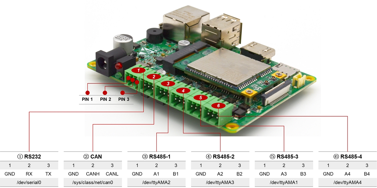
# RS232
CM4 Sensing has one RS232, it's the UART1 of the BCM2711 CPU. The RS-232 transceiver is SP3232. On the pre-installed OS, the RS232 port is the default Linux Serial Console, customers can connect to this RS232 port to login the Linux system and execute commands.
If you are using the origin Raspberry Pi OS, you should install our BSP package to enable the hardware feature. Please refer to section: Intall BSP by apt-get to install the BSP package.
Beside the Linux serial console, the RS232 port can also be configurated as a normal serial port.
This can be done by using raspi-config:
- Start raspi-config: sudo raspi-config.
- Select option 3 - Interface Options.
- Select option P6 - Serial Port.
- At the prompt Would you like a login shell to be accessible over serial? answer 'No'
- At the prompt Would you like the serial port hardware to be enabled? answer 'Yes'
- Exit raspi-config and reboot the Pi for changes to take effect.
WARNING
If RS232 is configurated as a normal serial port, the device node is /dev/serail0.
# RS485
There are 4 RS485 port on CM4 Sensing, they are all the UART ports on the BCM2711 CPU and the RS485 transceivers are SP3485. Please refer to the Interface Diagram to see the corresponding device node and pin definition.
WARNING
If you are using the origin Raspberry Pi OS, you should install our BSP package to enable the hardware feature. Please refer to section: Intall BSP by apt-get to install the BSP package.
# CAN Bus
There is a CAN bus on CM4 Sensing extended from SPI. The CAN network is can0.
For CAN configuration, please refer to:
pi@raspberrypi:~ $ ip link set can0 type can help
Usage: ip link set DEVICE type can
        [ bitrate BITRATE [ sample-point SAMPLE-POINT] ] |
        [ tq TQ prop-seg PROP_SEG phase-seg1 PHASE-SEG1
          phase-seg2 PHASE-SEG2 [ sjw SJW ] ]

        [ dbitrate BITRATE [ dsample-point SAMPLE-POINT] ] |
        [ dtq TQ dprop-seg PROP_SEG dphase-seg1 PHASE-SEG1
          dphase-seg2 PHASE-SEG2 [ dsjw SJW ] ]

        [ loopback { on | off } ]
        [ listen-only { on | off } ]
        [ triple-sampling { on | off } ]
        [ one-shot { on | off } ]
        [ berr-reporting { on | off } ]
        [ fd { on | off } ]
        [ fd-non-iso { on | off } ]
        [ presume-ack { on | off } ]

        [ restart-ms TIME-MS ]
        [ restart ]

        [ termination { 0..65535 } ]

        Where: BITRATE  := { 1..1000000 }
                  SAMPLE-POINT  := { 0.000..0.999 }
                  TQ            := { NUMBER }
                  PROP-SEG      := { 1..8 }
                  PHASE-SEG1    := { 1..8 }
                  PHASE-SEG2    := { 1..8 }
                  SJW           := { 1..4 }
                  RESTART-MS    := { 0 | NUMBER }
Customers can install can-utils to use cansend tools. Please refer to the open source project: https://github.com/linux-can/can-utils for detailed usage.
sudo apt update
sudo apt install can-utils
WARNING
If you are using the origin Raspberry Pi OS, you should install our BSP package to enable the hardware feature. Please refer to section: Intall BSP by apt-get to install the BSP package.
# Buzzer
There is a Buzzer on CM4 Sensing. You could control it just by writing the corresponding GPIO line GPIO11.
Open the Buzzer
sudo raspi-gpio set 11 op dh
Close the Buzzer
sudo raspi-gpio set 11 op dl
# Expansion Interfaces
# Mini PCIe
There is a Mini PCIe slot on CM4 Sensing. It can be installed some moudles like 4G, 5G and NPU etc. There's 1-lane PCIe Gen2, up to 5Gbps, and 1x USB 2.0 host.
We support 4G moudle from Quctel. Please refer to Ordering Code. We're also considering to support 5G.
# 5V@1A DC Output
J10 provides 5V@1A DC output. It can be used for Raspberry Pi 7" Touch Display or other purpose.