# Interfaces
# System
# RTC
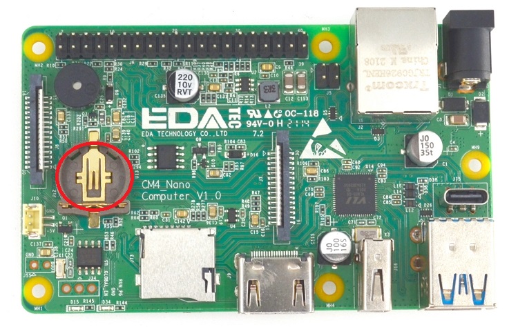
The CM4 Nano has an RTC module on board, and the RTC module should be mounted on the I2C0 bus to prepare to maintain the stable operation of the system time when the network is disconnected. Before testing, please make sure that the button battery with CR1220 mode is inserted under the power-off condition. as shown in the figure below:
- Set system time
sudo date -s "2021-08-15 00:00"
- Save system time to RTC:
sudo hwclock -w
- Read RTC time:
sudo hwclock
- Synchronize RTC to system time:
sudo hwclock -s
# Micro SD Card
CM4 NANO has an SD card interface onboard, which only can store the data, the system can not be booted from the SD card. Please note, SD Card interface occupies GPIO22-GPIO27 of 40pin connector, if you need to use either GPIO of GPIO22-GPIO27 for other function, you won't be able to use SD Card storage, otherwise conflicts will occur. If you really need to use GPIO22-GPIO27,please don't install SD Card into the SD socket.
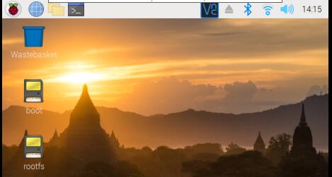
When you install SD Card into CM4 Nano, please make sure you shut down the system and Power Supply is disconnected. insert the SD card into the SD card slot of the CM4 Nano baseboard, and then power on to start the system. You can see the SD card icon on the desktop, as shown below:
# boot
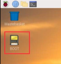
Short-circuit the BOOT pin and GND (J55) on CM4 Nano, which can prevent the normal startup of the system when it is powered on, and is used to program the system. For the detailed usage process, please refer to install (opens new window). (Do not short-circuit BOOT and GND in other scenarios, otherwise the system will not start normally).
# Network
# Wireless
The CM4 can be supplied with an onboard wireless module based on the Broadcom BCM43456 supporting both:
- 2.4 GHz, 5.0 GHz IEEE 802.11 b/g/n/ac wireless
- Bluetooth 5.0, BLE
NOTE: The wireless support is determined which CM4 purchased. Please refer to the ordering code for reference.
# Selection of Internal or External Antenna
It has an onboard PCB antenna, it also supports an external antenna.
The selection of internal or external antenna is done at boot time using the /boot/config.txt file, and can not be changed during operation.
sudo nano /boot/config.txt
select the internal antenna
dtparam=ant1
select the external antenna
dtparam=ant2
NOTE: Default is internal antenna
# Enable Wireless Network
The wireless networking on CM4 Nano is disabled for regulatory reasons, until the country code has been set. To set the country code:
Using the Desktop
open the Raspberry Pi Configuration application from the Preferences Menu, select Localisation and set the appropriate code.
Using the Command Line
sudo raspi-config
# Configuring Wireless Networking
Please refer to Raspberry Pi Documentation - Configuring Networking (opens new window)
# Ethernet
CM4 Nano has a Gigabit Ethernet interface on board. Before testing, please prepare a network cable and a router that can connect to the network. Connect the network cable and other necessary equipment. After power on, the system will automatically obtain an IP address.
ping www.baidu.com -I eth0
# Display
# Raspberry Pi Touch Display
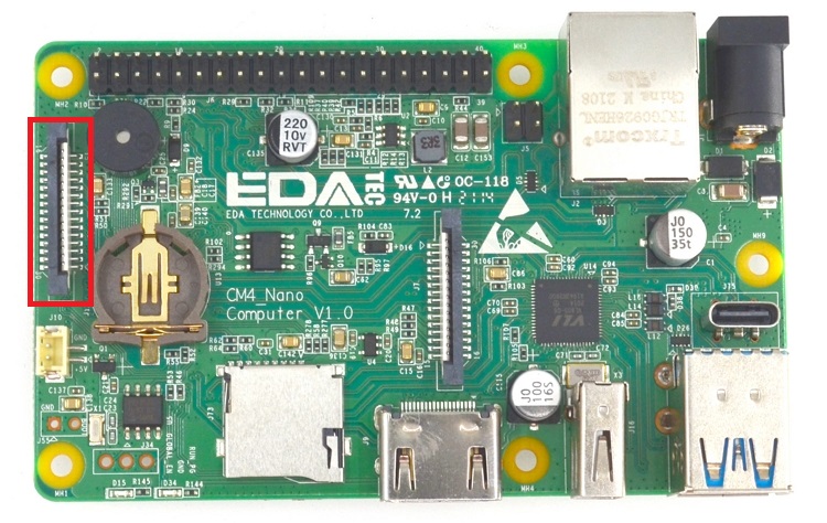
CM4 Nano provides a standard touch screen DSI interface (J8), which is connected to the official 7-inch touch screen for testing. Before testing, prepare a DSI cable and official touch screen. When disconnecting the power, pay attention to the insertion direction of the cable. The red wire is 5V and the black is GND, as shown in the following figure:
- After power on, you can see the system interface on the touch screen, as shown in the figure below:
# HDMI
After power on, you can see the system interface on the touch screen, as shown in the figure below:
sudo vi /boot/config.txt
framebuffer_width=1280
framebuffer_height=720
# Video
# Camera
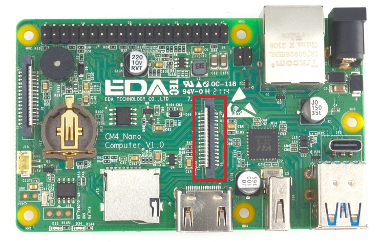
CM4 Nano provides 1 standard camera CSI interface (J7), which can be connected to the official Raspberry Pi camera for testing. Please prepare a CSI cable and an official camera before testing. Connect when the power is off. Please pay attention to the insertion direction of the cable when connecting, as shown in the figure below:
- After the system is powered on, open the terminal and enter the following command in the terminal to test:
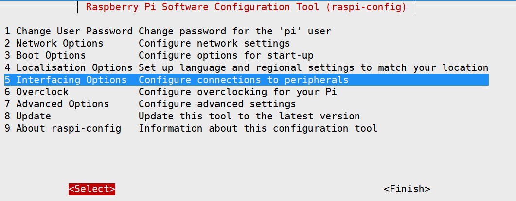
sudo raspi-config
- In the menu, select the fifth item, "Interfacing Options", as shown in the figure below:
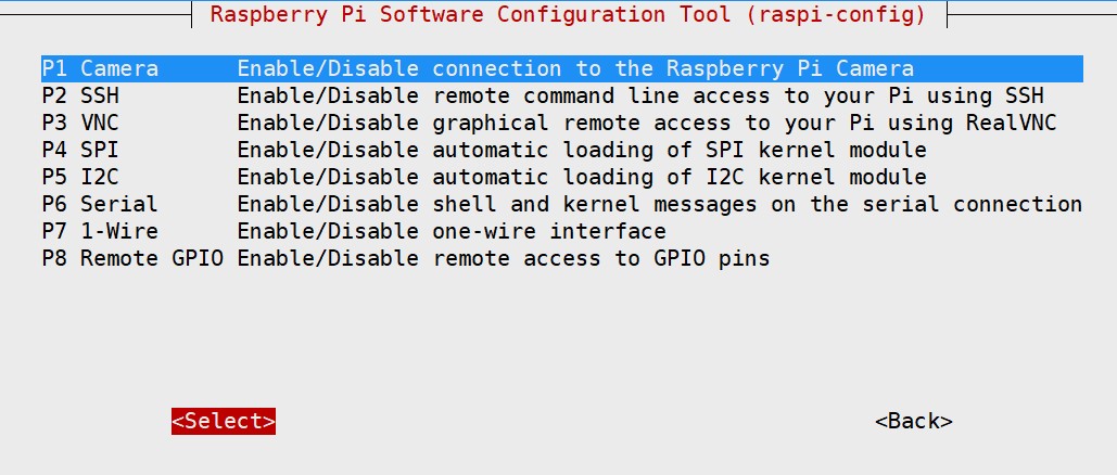
- Select Camera in the menu, as shown in the figure below:
- Select Yes as shown in the figure below:
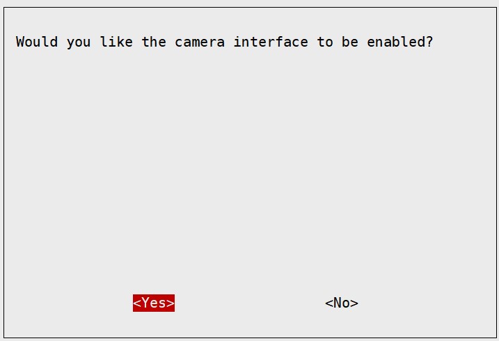
Exit the configuration menu and restart.
Photo test:
sudo raspistill -o 1.jpg
- Video test:
sudo raspivid -o 1.flv
# Connectivity
# USB 2.0
CM4 Nano has a USB 2.0 interface, which can be used to burn the system before starting (refer to "INSTALL (opens new window)"). After entering the system, it can also be used as a normal USB port to connect to a mouse or keyboard.
# Buzzer
CM4 NANO has a buzzer on board, which is controlled by the high and low levels of the GPIO6 pin. After entering the system, enter the following command in the terminal to test:
sudo echo 6 > /sys/class/gpio/export

sudo echo out > /sys/class/gpio/gpio6/direction
- Turn on the buzzer:
sudo echo 1 > /sys/class/gpio/gpio6/value
- Turn off the buzzer:
sudo echo 0 > /sys/class/gpio/gpio6/value
# USB 3.0
CM4 Nano has 3 USB 3.0 ports onboard, two of which are USB typeA Host, and the other is USB typeC host, which can be connected to a USB flash drive for testing. The USB typeC host test requires an additional USB adapter, as shown in the figure below:

- Insert the U disk to be tested into any USB 3.0 port, as shown in the figure below:

- Check the situation of the usb device, where Driver=usb-storage is the inserted U disk:
lsusb -t
/: Bus 02.Port 1: Dev 1, Class=root_hub, Driver=xhci_hcd/4p, 5000M
|__ Port 2: Dev 2, If 0, Class=Mass Storage, Driver=usb-storage, 5000M
/: Bus 01.Port 1: Dev 1, Class=root_hub, Driver=xhci_hcd/1p, 480M
|__ Port 1: Dev 2, If 0, Class=Hub, Driver=hub/4p, 480M
- Use hdparm software to test the speed of U disk
sudo hdparm -t /dev/sda
/dev/sda:
SG_IO: bad/missing sense data, sb[]: 70 00 05 00 00 00 00 14 00 00 00 00 20 00 00 00 00 00 00 00 00 00 00 00 00 00 00 00 00 00 00 00
Timing buffered disk reads: 380 MB in 3.01 seconds = 126.37 MB/sec
# Bluetooth
The cm4 module can optionally have a Bluetooth 5.0 BLE module on board for connecting to Bluetooth devices.
- Enter bluetootch shell
sudo bluetoothctl
- enable Bluetooth
power on

scan on
Discovery started
[CHG] Controller B8:27:EB:85:04:8B Discovering: yes
[NEW] Device 4A:39:CF:30:B3:11 4A-39-CF-30-B3-11
- Find the name of the Bluetooth device that is turned on, here the name of the Bluetooth device that is turned on for testing is test
devices
Device 6A:7F:60:69:8B:79 6A-7F-60-69-8B-79
Device 67:64:5A:A3:2C:A2 67-64-5A-A3-2C-A2
Device 56:6A:59:B0:1C:D1 Lefun
Device 34:12:F9:91:FF:68 test
- Pair the test device
pair 34:12:F9:91:FF:68
Attempting to pair with 34:12:F9:91:FF:68
[CHG] Device 34:12:F9:91:FF:68 ServicesResolved: yes
[CHG] Device 34:12:F9:91:FF:68 Paired: yes
Pairing successful
- Connect Bluetooth
trust 34:12:F9:91:FF:68
[CHG] Device 34:12:F9:91:FF:68 Trusted: yes
Changing 34:12:F9:91:FF:68 trust succeeded
# Expansion
# 40pin
CM4 Nano has expanded the standard 40pin pin to be compatible with the expansion modules on the market. Contains 17 GPIOs, plus the following peripherals (can also be used as GPIO): UART, I²C, SPI bus with two options, +3.3 V, +5 V, ground. Each GPIO pin can be defined as an input or output pin, or as other functions.
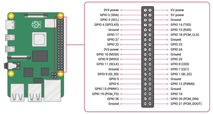
# Voltages
Two 5V pins and two 3V3 pins are present on the board, as well as a number of ground pins (0V), which are unconfigurable. The remaining pins are all general purpose 3V3 pins, meaning outputs are set to 3V3 and inputs are 3V3-tolerant.
# Outputs
A GPIO pin designated as an output pin can be set to high (3V3) or low (0V).
# Inputs
A GPIO pin designated as an input pin can be read as high (3V3) or low (0V). This is made easier with the use of internal pull-up or pull-down resistors. Pins GPIO2 and GPIO3 have fixed pull-up resistors, but for other pins this can be configured in software.
# More
As well as simple input and output devices, the GPIO pins can be used with a variety of alternative functions, some are available on all pins, others on specific pins.
PWM (pulse-width modulation)
- Software PWM available on all pins
- Hardware PWM available on GPIO12, GPIO13, GPIO18, GPIO19
- SPI
- SPI0: MOSI (GPIO10); MISO (GPIO9); SCLK (GPIO11); CE0 (GPIO8), CE1 (GPIO7)
- SPI1: MOSI (GPIO20); MISO (GPIO19); SCLK (GPIO21); CE0 (GPIO18); CE1 (GPIO17); CE2 (GPIO16)
- I2C
- Data: (GPIO2); Clock (GPIO3)
- EEPROM Data: (GPIO0); EEPROM Clock (GPIO1)
- Serial
- TX (GPIO14); RX (GPIO15)