# Interfaces
This chapter describes the hardware interfaces, and some hardware modules, including Pinout and some guides.
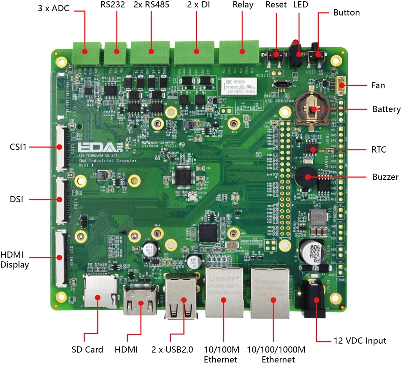
# Interface Diagram
# Top
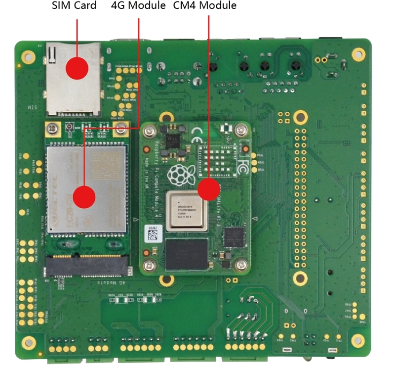
# Bottom
# System Functions
# Raspberry Pi CM4
- Broadcom BCM2711
- Quad-core, Cortex-A72, 1.5GHz ARM v8 64-bit CPU
- Support H.264, H.265 decoding, Support 4Kp60 video play
- Support H.264 encoding
- Support OpenGL EL 3.0
- DDR
- LPDDR4, up to 3200MT/s
- 1GB | 2GB | 4GB | 8GB
- Storage
- 8GB | 16GB | 32GB eMMC or micro SDCard
Customers can purchase CM4 with different configurations, please refer to Ordering Code
# Reset Button
There is a RESET button, S2, marked with RESET. Just push it to reset the system.
# User Button
There is also a USER button, S1, marked with USER, connecting to GPIO16. When the button is pushed, the GPIO16 with read as 0 or low level. Customers can use libgpiod (opens new window) to implment button event hander.
# RTC (Real Time Clock)
There is a RTC on CM4 Industrial. To use it, please make sure a CR1220 RTC battery is installed.
In the pre-installed Raspberry Pi OS, the RTC sync service is enabled default. The service can automaticlly sync clock betweeen RTC and system clock:
- When boot up, the service will get the clock from RTC and update the system clock with it
- If CM4 Industrial has Internet accessing, the system clock will sync with the NTP server.
- When system poweroff, the service write the system clock to RTC
- Thanks to the CR1220 battery, the clock is continually running when the CM4 Industrial is turned on or off
In this way, we can get a reliable clock.
TIP
Note: If it is the first time boot up, there is no valid date in RTC, and this will result sync to system clock failed. Don't worry, Just reboot and it will be Okay.
If you don't want this service, you clould disable it manually:
sudo systemctl disable rtc
sudo reboot
Re-enable the service
sudo systemctl enable rtc
sudo reboot
# RTC Manually Operation
Read clock from RTC
sudo hwclock -r
Sync RTC clock to system clock
sudo hwclock -s
Write system clock to RTC
sudo hwclock -w
# Trouble Shooting
First, please check if the RTC device(/dev/rtc0) is loaded:
ls /dev/rtc0
If no, you may use the original Raspberry Pi OS without our BSP installed, Please refer to section: Intall BSP by apt-get to install the BSP package. You may also want to install ed-rtc package to enable RTC automatically sync service.
Some other possible doubts:
- No CR1220 battery installed
- Internet is necessary to sync time from Internet. Besides, you should enable
UDP 123port.
# Storage
# micro SD Slot
The micro SD Slot is the main storage when you purchase CM4 Industrial without eMMC.
WARNING
The micro SDCard can only be used when you purchase CM4 Industrial with the CM4 Lite Module(without eMMC). When you use one with eMMC, you cannot use the micro SDCard slot.
# SPI Flash
There is a 32Mbits / 4MBytes SPI Flash on CM4 Industrial. This can be used for data storage. On Linux, it is offten identified as a MTD (Memory Technology Device) device, On CM4 Industrial, the device file is /dev/mtd0
WARNING
MTD devices are different from block devices like HDD, SDCard, u-disk and eMMC. For MTD devices, it always should be erased before write. The erase unit is sector and program unit is page. A sector is always many pages. But for block devices, it's hardware to do erase. From host view, it does not distinguish between eraes and write. But for MTD deivces, Host should.
We offten use JFFS2 filesystem to manage MTD device, not ext4.
WARNING
This feature is default enabled in the pre-installed OS. If you use the origin Raspberry Pi OS, you should intall the BSP package first to use the MIPI DSI. Please refer to section: Intall BSP by apt-get to install the BSP package.
- Install
mtd-utilsto manage the flash device
sudo apt update
sudo apt install mtd-utils
- You should format / erase the device, before you use
sudo flash_erase /dev/mtd0 0 0
- Mount with
JFFS2type
sudo mount -t jffs2 /dev/mtd0 /mnt
Then, you can read / write the device by /mnt.
# Camera
There are 2 x CSI on CM4 Industrial. marked with CSI1 and CSI0, supporting Raspberry Pi official 5M & 8M cameras.
WARNING
This feature is default enabled in the pre-installed OS. If you use the origin Raspberry Pi OS, you should intall the BSP package first to use the MIPI DSI. Please refer to section: Intall BSP by apt-get to install the BSP package.
Before use the camera, you should enable it by raspi-config
- Enable the camera
sudo raspi-config
Select Interfacing Options -> Camera, then press ENTER, and select Yes. navigate to Finish. Then it will promote if to make a reboot. Just reboot to take effect.
- Detect attahced cameras
vcgencmd get_camera
supported=1 detected=1
supported means how many cameras enabled in configuraiton. detected means how many cameras attached have been detected.
- Take a photo
raspistill -o Desktop/image.jpg

# Can specifiy width and height
raspistill -o Desktop/image-small.jpg -w 640 -h 480
- Take a video
# 10 seconds
raspivid -o Desktop/video.h264 -t 10000
TIP
When the camera cannot be used, please make sure:
- If use our BSP pre-installed image. If use the origin Raspberry Pi OS, please install our BSP first
- Have you enable the camera by
raspi-config? - You could run
vcgencmd get_camerato detect first
# CSI0 Pin Definition
| Pin Number | Pin Name | CM4 Pin Name | CM4 Pin ID |
|---|---|---|---|
| 1 | GND | ||
| 2 | CAM0_D0_N | CAM0_D0_N | 128 |
| 3 | CAM0_D0_P | CAM0_D0_P | 130 |
| 4 | GND | ||
| 5 | CAM0_D1_N | CAM0_D1_N | 134 |
| 6 | CAM0_D1_P | CAM0_D1_P | 136 |
| 7 | GND | ||
| 8 | CAM0_CLK_N | CAM0_C_N | 140 |
| 9 | CAM0_CLK_P | CAM0_C_P | 142 |
| 10 | GND | ||
| 11 | CAM0_GPIO | Camera_GPIO | 97 |
| 12 | GND | ||
| 13 | ID_SC | ID_SC | 35 |
| 14 | ID_SD | ID_SD | 36 |
| 15 | 3V3 | ||
| 16 | GND | ||
| 17 | GND |
# CSI1 Pin Definition
| Pin ID | Pin Name | CM4 Pin Name | CM4 Pin ID |
|---|---|---|---|
| 1 | GND | ||
| 2 | CAM1_D0_N | CAM1_D0_N | 115 |
| 3 | CAM1_D0_P | CAM1_D0_P | 117 |
| 4 | GND | ||
| 5 | CAM1_D1_N | CAM1_D1_N | 121 |
| 6 | CAM1_D1_P | CAM1_D1_P | 123 |
| 7 | GND | ||
| 8 | CAM1_CLK_N | CAM1_C_N | 127 |
| 9 | CAM1_CLK_P | CAM1_C_P | 129 |
| 10 | GND | ||
| 11 | CAM1_GPIO | Camera_GPIO | 97 |
| 12 | GND | ||
| 13 | SCL0 | SCL0 | 80 |
| 14 | SDA0 | SDA0 | 82 |
| 15 | 3V3 | ||
| 16 | GND | ||
| 17 | GND |
# Display
CM4 Industrial has Triple Display channels and could could feed 2 devices simultaneously.
- If you use the Desktop version of Raspberry Pi OS, you can set it by
Menu -> Preferences -> Screen Configuration - If you use Lite version of Raspberry Pi OS, please refer to xrandr (opens new window)
# Standard HDMI A
CM4 Industrial has a standard HDMI Type A port. Just plug to a HDMI monitor and it will work.
# HDMI FPC Connector
J65 is another HDMI port but in FPC connctor form-factor. It has USB 2.0 signals for touch, PWM for brightness. We are developing a new HDMI Touch Display, you could get in touch with the Sales for the latest status.
# Pin Definition
| Pin ID | Pin Name | CM4 Pin Name | CM4 Pin ID |
|---|---|---|---|
| 1 | NA | ||
| 2 | NA | ||
| 3 | NA | ||
| 4 | NA | ||
| 5 | GND | ||
| 6 | USB_DP4 | DP4 | |
| 7 | USB_DM4 | DM4 | |
| 8 | GND | ||
| 9 | HDMI1_HPD | HOTPLUG | 143 |
| 10 | HDMI1_SCL | SCL | 147 |
| 11 | HDMI1_SDA | SDA | 145 |
| 12 | GND | ||
| 13 | HDMI1_TX2P | TX2_P | 146 |
| 14 | HDMI1_TX2N | TX2_N | 148 |
| 15 | GND | ||
| 16 | HDMI1_TX1P | TX1_P | 152 |
| 17 | HDMI1_TX1N | TX1_N | 154 |
| 18 | GND | ||
| 19 | HDMI1_TX0P | TX0_P | 158 |
| 20 | HDMI1_TX0N | TX0_N | 160 |
| 21 | GND | ||
| 22 | HDMI1_CLKP | CLK_P | 164 |
| 23 | HDMI1_CLKN | CLK_N | 166 |
| 24 | GND | ||
| 25 | BACKLIGHT_PWM | GPIO18 | 49 |
| 26 | GND | ||
| 27 | GND | ||
| 28 | GND | ||
| 29 | GND | ||
| 30 | GND | ||
| 31 | GND | ||
| 32 | LCD_PWR_EN | GPIO23 | 47 |
| 33 | 5V | ||
| 34 | 5V | ||
| 35 | 5V | ||
| 36 | 5V | ||
| 37 | 5V | ||
| 38 | 5V | ||
| 39 | 5V | ||
| 40 | 5V |
# MIPI DSI Connector
J61 is the MIPI DSI connector in FPC form-factor. It supports the official Raspberry Pi 7" Touch Display. We also sale this product, refer to: 7” Touch Display (opens new window)
J72 is a 5V@1A DC power output, it can provide power for the Raspberry Pi 7" Touch Display.
MIPI DSI is enabled default in the pre-installed OS. If you use the origin Raspberry Pi OS, you should intall the BSP package first to use the MIPI DSI. Please refer to section: Intall BSP by apt-get to install the BSP package.
# DSI1 Pin Definition
| Pin ID | Pin Name | CM4 Pin Name | CM4 Pin ID |
|---|---|---|---|
| 1 | GND | ||
| 2 | DSI1_D1_N | DSI1_D1_N | 181 |
| 3 | DSI1_D1_P | DSI1_D1_P | 183 |
| 4 | GND | ||
| 5 | DSI1_CLK_N | DSI1_C_N | 187 |
| 6 | DSI1_CLK_P | DSI1_C_P | 189 |
| 7 | GND | ||
| 8 | DSI1_D0_N | DSI1_D0_N | 175 |
| 9 | DSI1_D0_P | DSI1_D0_P | 177 |
| 10 | GND | ||
| 11 | SCL0 | SCL0 | 80 |
| 12 | SDA0 | SDA0 | 82 |
| 13 | GND | ||
| 14 | 3V3 | ||
| 15 | 3V3 | ||
| 16 | GND | ||
| 17 | GND |
# Wired Interfaces
# Gigabit-Ethernet
CM4 Industrial has a 10 / 100 / 1000Mbsp Ethernet, marked with 10/100/1000. We suggest to use Cat6 Ethernet cable. In Raspberry Pi OS, it uses DHCP to get IP address default. If you want to set a static IP address, please refer to the usage of dhcpcd: manual of dhcpcd (opens new window)
TIP
It is always eth0 on CM4 Industrial.
# Fast-Ethernet
CM4 Industrial also has a 10 / 100Mbsp Ethernet, marked with 10/100.
WARNING
This feature is default enabled in the pre-installed OS. If you use the origin Raspberry Pi OS, you should intall the BSP package first to use the MIPI DSI. Please refer to section: Intall BSP by apt-get to install the BSP package.
A MAC address has been programed. If you want to program your own MAC address, we provide a script to do that.
git clone https://gist.github.com/8c5c05e1bf22eff4e6ea76ae429f377a.git lan-utils
cd lan-utils
./lan9500-mac-addr-set.sh

Usage:  { prog addr | read | erase }
- Read current MAC address
sudo ./lan9500-mac-addr-set.sh read
- Erase
sudo ./lan9500-mac-addr-set.sh earse
- Program and do a reboot to take effect
sudo ./lan9500-mac-addr-set.sh prog aa:bb:cc:dd:ee:ff

Program MAC address: aa:bb:cc:dd:ee:ff...... OK

sudo reboot
# USB 2.0 Host Type-A
CM4 Industrial has 2 USB 2.0 Type A ports. The USB 2.0 Host is default enabled in the pre-installed OS. If you use the origin Raspberry Pi OS, you should intall the BSP package first. Please refer to section: Intall BSP by apt-get to install the BSP package.
# USB 2.0 Host Pin Header
There're also another 2x USB 2.0 pin header for internal expansion, J44 and J63.
WARNING
This feature is default enabled in the pre-installed OS. If you use the origin Raspberry Pi OS, you should intall the BSP package first to use the MIPI DSI. Please refer to section: Intall BSP by apt-get to install the BSP package.
# USB micro-B
J73 is the USB micro-B port, it's mainly used for eMMC Flashing. You could also use it to make the CM4 Industrial as a USB peripheral device such as a mass-storage device. For eMMC Flashing, please refer to eMMC Flashing
# Wireless
CM4 Industrial provide rich wireless network support, including Dual-band WiFi, Bluetooth 5.0 and optional 4G LTE.
# Dual-band WiFi
The CM4 Industrial can be supplied with an onboard wireless module supporting both:
- 2.4 GHz, 5.0 GHz IEEE 802.11 b/g/n/ac wireless
- Bluetooth 5.0, BLE
The CM4 Industrial has an onboard antenna. If used it should be positioned in the product such that it is not surrounded by metal, including any ground plane. Alternatively, the CM4 Industrial has an external antenna which is certified when you purchase CM4 Industrial with WiFi and metal case.
# Enable WiFi
You should set the country code for your wireless network before you use. If you use a Desktop OS, please refer to: Raspberry pi Documentation - Configuring Networking - Using the Desktop (opens new window), If you use a Lite version OS, please refer to: Raspberry pi Documentation - Configuring Networking - Using the Command Line (opens new window).
# Internal or External Antenna
WARNING
the default WiFi antenna setting of pre-intalled OS is internal antenna. If you purchase CM4 Industrial WiFi metal case and external antenna, you should update the settings.
Edit /boot/config.txt
sudo nano /boot/config.txt
For external antenna, add:
dtparam=ant2
For internal antenna, add:
dtparam=ant1
# AP
WiFi can also be configured to AP mode.
a Routed Wireless Access Point
                                        +- RPi -------+
                                     +---+ 10.10.0.2   |          +- Laptop ----+
                                     |   |     WLAN AP +-)))  (((-+ WLAN Client |
                                     |   | 192.168.4.1 |          | 192.168.4.2 |
                                     |   +-------------+          +-------------+
                 +- Router ----+     |
                 | Firewall    |     |   +- PC#2 ------+
(Internet)---WAN-+ DHCP server +-LAN-+---+ 10.10.0.3   |
                 |   10.10.0.1 |     |   +-------------+
                 +-------------+     |
                                     |   +- PC#1 ------+
                                     +---+ 10.10.0.4   |
                                         +-------------+
a Bridged Wireless Access Point
                                         +- RPi -------+
                                     +---+ 10.10.0.2   |          +- Laptop ----+
                                     |   |     WLAN AP +-)))  (((-+ WLAN Client |
                                     |   |  Bridge     |          | 10.10.0.5   |
                                     |   +-------------+          +-------------+
                 +- Router ----+     |
                 | Firewall    |     |   +- PC#2 ------+
(Internet)---WAN-+ DHCP server +-LAN-+---+ 10.10.0.3   |
                 |   10.10.0.1 |     |   +-------------+
                 +-------------+     |
                                     |   +- PC#1 ------+
                                     +---+ 10.10.0.4   |
                                         +-------------+
More details please refer to open source project: github: garywill/linux-router (opens new window)
# Bluetooth 5.0
Customers can use bluetoothctl to discover, pair and connect a bluetooth device. Please refer to: ArchLinux - Wiki - Bluetooth (opens new window)
# 4G LTE
The 4G LTE is optional. Customers should use the pre-installed OS. If it's the origin Raspberry Pi OS, Customers should install our BSP package to enable the hardware feature. Please refer to section: Intall BSP by apt-get to install the BSP package, then you should also install ed-networkmanager package.
sudo apt install ed-networkmanager
sudo reboot
# Set the 4G connection
Use this command to set a gsm connection
# sudo nmcli connection add type gsm con-name <connection_name>
# set a gsm connection named mobilegsm
sudo nmcli connection add type gsm con-name mobilegsm
TIP
If the above command does not work, here is some examples, you can follow examples to create a connection
# sudo nmcli connection add type gsm con-name <mobile> ifname cdc-wdm0 gsm.number <number> gsm.apn <apn> gsm.username <username> gsm.password <password>
# China Mobile
sudo nmcli connection add type gsm con-name "mobile" ifname cdc-wdm0 gsm.number "*98*1#" gsm.apn "cmnet"
# China Unicom
sudo nmcli connection add type gsm con-name "Unicom" ifname cdc-wdm0 gsm.number "*99#" gsm.apn "3gnet"
# China Telecom
sudo nmcli connection add type gsm con-name "Telecom" ifname cdc-wdm0 gsm.number "#777" gsm.username "ctnet@mycdma.cn" gsm.password "vnet.mobi"
Serveral minutes after reboot, you could check the connction by ifconfig
# Trouble Shooting
Please make sure:
- micro SIM card is inserted
- If the 4G antenna is pluged
- If the OS is the origin Raspberry Pi OS, please install our BSP and
ed-networkmanagerpackages first - Try to reset SIM card
raspi-gpio set 10 pd
raspi-gpio set 10 op dl
raspi-gpio set 10 dh
raspi-gpio set 10 dl
sudo reboot
Customers could check if the BSP is installed:
dpkg -l | grep ed-cm4ind
dpkg -l | grep ed-networkmanager
# Industial Interfaces
CM4 Industrial has rich industrial buses, including:
- 1x RS232
- 1x Serial (TTL)
- 2x RS485
- 2x isolated DI
- 1x DPDT Relay
- 1x Buzzer
# Table of Linux Device Files
| ID | BCM2711 Peripheral ID | Linux Device File (V1.1) | Linux Device File (V1.2) | Linux Device File (V1.3) |
|---|---|---|---|---|
| J58 / UART0, Pin Header | UART1 | /dev/serial0 | /dev/serial0 | /dev/serial0 |
| RS485-1 | UART4 | /dev/ttyAMA2 | /dev/ttyAMA2 | /dev/ttyAMA2 |
| RS485-2 | UART3 | /dev/ttyAMA1 | /dev/ttyAMA1 | /dev/ttyAMA1 |
| RS232 | UART5 | /dev/ttyAMA3 | /dev/ttyAMA3 | /dev/ttyAMA3 |
| DIN1 | GPIO11 | |||
| DIN2 | GPIO26 | |||
| Relay | GPIO22 | |||
| ADC - AIN1 | in_voltage4_raw | N/A | in_voltage1_raw | |
| ADC - AIN2 | in_voltage6_raw | N/A | in_voltage2_raw | |
| ADC - AIN3 | in_voltage7_raw | N/A | in_voltage3_raw | |
| Buzzer | GPIO25 | |||
| J68, 1xGPIO | GPIO27 |
# Serial / UART (TTL)
J58, marked with UART0, 1x4 2.54mm Pin Header, is a TTL Serial, connected with UART1 on BCM2711.
On the BSP pre-installed OS, the serial port is the default Linux Serial Console, customers can connect to this port to login the Linux system and execute commands.
If you are using the origin Raspberry Pi OS, you should install our BSP package to enable the hardware feature. Please refer to section: Intall BSP by apt-get to install the BSP package.
Beside the Linux serial console, this serial port can also be configurated as a normal serial port.
This can be done by using raspi-config:
- Start raspi-config: sudo raspi-config.
- Select option 3 - Interface Options.
- Select option P6 - Serial Port.
- At the prompt Would you like a login shell to be accessible over serial? answer 'No'
- At the prompt Would you like the serial port hardware to be enabled? answer 'Yes'
- Exit raspi-config and reboot the Pi for changes to take effect.
WARNING
If the serial port is configurated as a normal serial port, the device node is /dev/serial0.
# RS232
There is 1x RS232 on CM4 Industrial. The RS-232 transceiver is SP3232. Please refer to above Table of Linux Device Files for the corresponding device file.
If you are using the origin Raspberry Pi OS, you should install our BSP package to enable the hardware feature. Please refer to section: Intall BSP by apt-get to install the BSP package.
# RS485
There're 2x RS485 on CM4 Industrial. The RS-485 transceiver is SP3485. Please refer to above Table of Linux Device Files for the corresponding device file.
If you are using the origin Raspberry Pi OS, you should install our BSP package to enable the hardware feature. Please refer to section: Intall BSP by apt-get to install the BSP package.
# ADC
There're 3 ADC channels on CM4 Industrial. Take AIN1 as the example to show how to read the AD convert value:
cd /sys/bus/iio/devices
cd iio\:device0

# On CM4 Industrial V1.1, in_voltage4_raw is the AIN1
cat in_voltage4_raw
WARNING
ADC part is different on different CM4 Industrial hardware version. Please refer to above Table of Linux Device Files for the corresponding device file:
- The ADC chip is STMPE811 on hardware V1.1, refer to the datasheet (opens new window)
- No ADC chip on hardware V1.2
- The ADC chip is ADS1015 on hardware V1.3, refer to the datasheet (opens new window)
# Relay
CM4 Industrial has a DPDT relay, it's controlled by GPIO22:
GPIO22 is default low level, and the default state of Relay is
normal close: COM1 is connected to NC1 and COM2 is connected to NC2.When the GPIO22 is set to high level, the relay state will be
normal open: COM1 is connected to NO1 and COM2 is connected to NO2.Open Relay
sudo raspi-gpio set 22 op dh
- Close Relay
sudo raspi-gpio set 22 op dl
# Buzzer
There is a Buzzer on CM4 Industrial. You could control it just by writing the corresponding GPIO line GPIO25.
Open the Buzzer
sudo raspi-gpio set 25 op dh
Close the Buzzer
sudo raspi-gpio set 25 op dl
# GPIO Pin Header
There is 1x2 2.54mm pin header GPIO, connect to GPIO27. Customers can use raspi-gpio to control this IO.
# Expansion Interfaces
# Mini PCIe
There is a Mini PCIe slot on CM4 Industrial. It can be installed some moudles like 4G, 5G and NPU etc. There's 1-lane PCIe Gen2, up to 5Gbps, and 1x USB 2.0 host.
We support 4G moudle from Quctel. Please refer to Ordering Code. We're also considering to support 5G.
# 40-PIN GPIO, Compatible with Raspberry Pi HAT
There is a 40-PIN GPIO on CM4 Industrial, compatible with Raspberry Pi HAT, just like the one on Raspberry Pi 4B. It supports many Raspberry Pi HAT expansion boards like isolated DI / DO, CAN bus support, PoE support and etc.
WARNING
Note: There're some GPIO lines already used by CM4 Industrial. Make sure do not make conflict.
# 5V@1A DC Output
J72 provides 5V@1A DC output. It can be used for Raspberry Pi 7" Touch Display or other purpose.
# FAN Connector
J67 provides FAN support could be enable and disable.
# Pin Definition
| Pin ID | Pin Name | CM4 Pin Name | Remark |
|---|---|---|---|
| 1 | 5V_PWR | 5V FAN power | |
| 2 | TACHO | No used. Pulled up to 5V with 100K resistor. | |
| 3 | EN | GPIO24 | Can only support enable and disable. No PWM support |
| 4 | GND | ||
| 5 | GND |